Module sine_generator
This document contains technical documentation for the sine_generator module.
To browse the source code, visit the repository on GitHub.
This module contains a flexible and robust sinusoidal waveform generator written in VHDL. Also known as a direct digital synthesizer (DDS), numerically-controlled oscillator (NCO), or a sine/sinus wave generator. This is a very common component when doing any kind of signal processing, signal analysis or modulation in an FPGA or ASIC.
Key features
SFDR of 192 dB in fractional phase mode.
Theoretically unlimited SFDR in integer phase mode.
Both sine and cosine outputs, for I/Q modulation and other applications.
Synthesizes frequencies all the way up to Nyquist.
Written in pure VHDL. Needs no separate Matlab/Python tools to pre-calculate anything.
Better performance and lower resource footprint compared to other implementations.
The implementation is based around a quarter-wave lookup table in block RAM. It supports both integer and fractional phase modes, and can be parameterized to use dithering and Taylor expansion to increase the performance, when necessary. It is well-tested and well-analyzed. The performance is proven by theory as well as simulation and on-device tests.
Quick start guide
The theory behind this module is somewhat complex, and it has a number of parameters that must be assigned and understood in order for things to work as intended. While reading this full document is recommended for a full insight, below is a quick step-by-step guide to utilizing the module.
Determine the Frequency resolution requirement of your application.
Decide if you will use Integer or fractional phase mode, given your requirements.
Parameterize the module to reach the desired performance, using either
Determine your phase increment value based on About phase increment.
Instantiate the sine_generator.vhd entity in your design and start oscillating.
Note
The performance of the module is measured in terms of the spurious-free dynamic range (SFDR) of the output signal. See https://en.wikipedia.org/wiki/Spurious-free_dynamic_range if you are not familiar with this.
Frequency resolution
Frequency resolution is defined as the smallest output frequency step that can be taken by adjusting
phase_increment.
It is given by
Where clk_frequency_hz is the frequency of the system clock that is clocking this module,
and the memory_address_width and phase_fractional_width are generics to this module.
The resolution required depends on the application of the module, and must be determined by
the user.
Integer or fractional phase mode
If the Frequency resolution requirement of your system can be satisfied with
phase_fractional_width kept at zero, the module can operate in “integer phase” mode which has
many benefits.
Otherwise the module must operate in “fractional phase” mode, which comes with some drawbacks.
Note that the module will always use a memory that is
large, and you must hence choose a maximum memory size that your design can afford.
The memory_data_width is typically 18 and memory_address_width between 9 and 12, since
that maps very nicely to BRAM primitives.
But they can be both less or more.
Parameterize in integer phase mode
In integer phase mode, the performance is limited only by the memory_data_width generic value
(see About integer phase mode for details).
The SFDR of the output signal is at least
Use this equation to determine the memory_data_width generic value you need, given your
SFDR requirement.
There is no need to adjust any other generic value to the generator top level.
Parameterize in fractional phase mode
If we reorder the Frequency resolution equation above, we get
Use this to calculate the phase_fractional_width generic value needed.
When in fractional phase mode, the performance is limited mainly by the memory_address_width
generic value (see About fractional phase mode for details).
It can be improved by enabling Fractional phase with dithering or Fractional phase with Taylor expansion.
See the performance equations below to determine your required memory_address_width generic
value, and whether you want to set enable_phase_dithering or enable_first_order_taylor.
Note that that in all cases using fractional phase mode, the memory_data_width generic must have
a value of at least
in order for the performance to not be limited by quantization noise. A value of 18 is typical, since it maps nicely to a BRAM primitive, but it might have to be increased in extreme performance scenarios.
Base fractional performance
If neither dithering nor Taylor expansion is enabled, the SFDR of the output signal is at least
Use this equation to determine the memory_address_width generic value you need, given your
SFDR requirement.
Performance with phase dithering
When the Fractional phase with dithering feature is enabled, the SFDR of the output signal is improved to at least
Use this equation to determine the memory_address_width generic value you need, given your
SFDR requirement.
Performance with Taylor expansion
When the Fractional phase with Taylor expansion feature is enabled, the SFDR of the output signal is improved to at least
Use this equation to determine the memory_address_width generic value you need, given your
SFDR requirement.
About integer phase mode
In integer phase mode, the phase, which is an accumulation of the input phase_increment,
will always point exactly to an integer memory address.
Hence there is no truncation of the phase and no phase error.
See Parameterize in integer phase mode for an SFDR performance equation.
This means that the accuracy of the result is limited only by the bit width of the sine
samples in memory (memory_data_width).
And not at all by the number of samples in the memory (memory_address_width).
This leads to very high performance in typical scenarios.
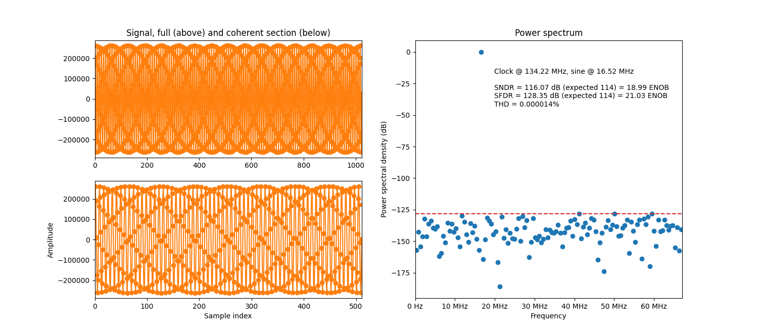
Example simulation with an integer phase increment.
Note
Enabling dithering or Taylor expansion does nothing for the performance in integer phase mode. This is because both of these mechanisms work on the phase error, which is zero in integer phase mode.
About fractional phase mode
In fractional phase mode, the phase will not always point exactly to a memory address. Hence the phase is truncated, which leads to an error in the result. I.e. worse performance. See Base fractional performance for an SFDR performance equation.
The example simulation plot below has the same configuration as the integer phase example above, except that the target sine frequency is slightly adjusted to require five fractional phase increment bits. The massive drop in performance is clearly visible.
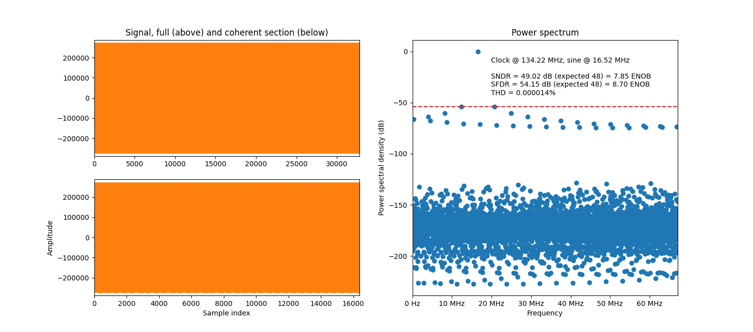
Example simulation with a fractional phase increment.
In this mode the input port phase_increment needs fractional bits in order to express the
desired sine frequency.
The generic phase_fractional_width must be set to a non-zero value so the desired frequency
resolution is reached.
Fractional phase with dithering
Phase dithering can be enabled to increase the performance in fractional phase mode by setting
the enable_phase_dithering generic.
See Performance with phase dithering for an SFDR performance equation.
See also here for implementation details.
The result of simulating the example scenario from About fractional phase mode above, but with dithering enabled, is shown below.
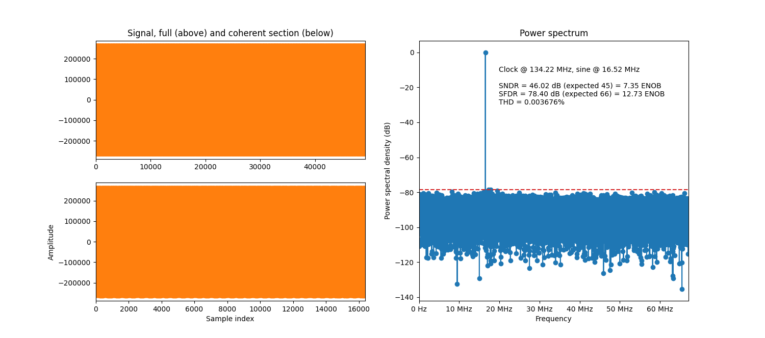
Example simulation with a fractional phase increment and dithering.
As can be seen when comparing the performance to the non-dithered ditto above, the SFDR is better but the SNDR is worse. One can also note that the noise floor is much more uniformly spread out.
Fractional phase with Taylor expansion
Taylor expansion can be enabled to increase the performance in fractional phase mode by setting
the enable_first_order_taylor generic.
See Performance with Taylor expansion for an SFDR performance equation.
See also here for a background on the Taylor expansion concept.
The result of simulating the example scenario from About fractional phase mode above, but with first-order Taylor expansion enabled, is shown below.
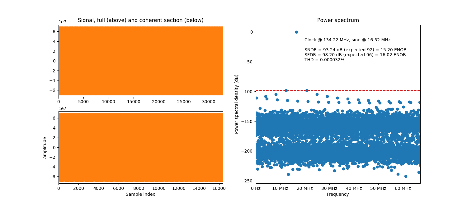
Example simulation with a fractional phase increment and Taylor expansion.
As can be seen in the plot, both the SNDR and SFDR are massively improved. Compared to the non-Taylor-expanded ditto above, the performance is roughly doubled. Other than that, the noise floor is quite similar with distinct distortion peaks, but they are all suppressed more by the Taylor expansion.
sine_calculator.vhd
Calculates the sinus value corresponding to the provided phase value. Instantiates a sine lookup table (sine_lookup.vhd) where the integer part of the phase will be used as address.
If fractional phase is enabled, the fractional part of the phase will be truncated when forming the lookup address. First-order Taylor expansion can be enabled to improve the accuracy using the truncated phase.
Taylor expansion
The Taylor expansion of a function is given by
See https://en.wikipedia.org/wiki/Taylor_series. The accuracy is better if \(a\) is close to \(x\), or if many terms are used. Substituting
and realizing the following properties of the derivative of the sine function
we get
Taylor expansion implementation
This entity corrects the sine lookup value using first-order Taylor expansion, meaning
In this representation, \(x\) is the full phase value, including fractional bits. The \(a\) is the integer part of the phase value that forms the memory address, and \(e\) is the fractional part of the phase that gets truncated. The \(A \sin(B x + C)\) and \(A \cos(B x + C)\) values are given by sine_lookup.vhd. The \(B\) value is the phase increment of the lookup table:
The calculation is partitioned like this, using DSP48 blocks:
![digraph my_graph {
graph [dpi=300];
rankdir="LR";
phase_error [shape="none" label="phase error"];
pi [shape="none" label="π/2"];
{
rank=same;
phase_error;
pi;
}
first_multiplication [shape="box" label="x"];
phase_error -> first_multiplication [label="<=25"];
pi -> first_multiplication [label="<=18"];
lookup_cosine [shape="none" label="lookup cosine"];
{
first_multiplication=same;
lookup_cosine;
pi;
}
second_multiplication [shape="box" label="x"];
first_multiplication -> second_multiplication [label="<=25"];
lookup_cosine -> second_multiplication [label="<=18"];
lookup_sine [shape="none" label="lookup sine & 0"];
{
first_multiplication=same;
second_multiplication;
lookup_sine;
}
addition [shape="box" label="+"];
second_multiplication -> addition [label="<=47"];
lookup_sine -> addition [label="<=47"];
saturation [shape="box" label="saturation"];
addition -> saturation [label="<=48"];
result [shape="none" label="result"];
saturation -> result;
}](../../_images/graphviz-c51c10a0b16deee2d99949ecac417d7af3c32d5c.png)
The \(\pi / 2\) is handled as a fixed-point value with a number of fractional bits determined to give sufficient performance. Multiplying with the phase error, which is a fractional value, and then the cosine value gives a value that has a very high number of fractional bits. In order for the summation with the sine value to be correct, the sine value must be shifted up until the binal points align.
When the operands are small, the last multiplication and the addition can fit in the same DSP48. This is not the case in general though.
Note
An alternative approach would be to store the error term in a ROM and use the phase error as lookup address. This would save DSP blocks but cost BRAM. We can support that in the future with a generic switch if there is ever a need.
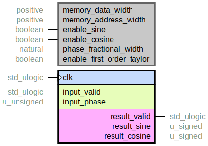
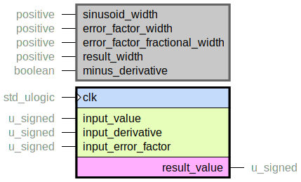
sine_generator.vhd
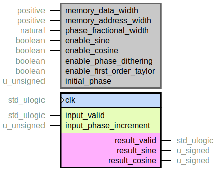
This sinus generator top level accumulates the incoming phase_increment to form a
phase value.
The sine_calculator.vhd is instantiated to calculate sinusoid values
based on this phase.
Set the enable_sine and enable_cosine generic parameters to enable sine and/or
cosine output.
If fractional phase is enabled, the fractional part of the phase will be truncated in sine_calculator.vhd when forming the lookup address. Phase dithering can be enabled in this case to improve the SFDR.
About phase increment
The frequency of the output signal is determined by the phase_increment input port value.
The width of this port is equal to
In VHDL you are recommended to utilize the get_phase_width function in
sine_generator_pkg.vhd.
The phase increment value can be calculated as
Where sine_frequency_hz is the target sinus output frequency, and clk_frequency_hz is
the frequency of the system clock that is clocking this module.
In VHDL you are recommended to utilize the get_phase_increment function in
sine_generator_pkg.vhd.
Note that the Nyquist condition must be honored, meaning that the sine frequency must be less than half the clock frequency.
Phase dithering
Phase dithering adds a pseudo-random offset to the phase that is sent to sine_calculator.vhd. The phase offset is uniformly distributed over the entire fractional phase width, meaning between 0 and almost 1 LSB of the memory address. The phase offset is added on top of the phase accumulator, and sometimes the addition will result in +1 LSB in the address, sometimes it will not.
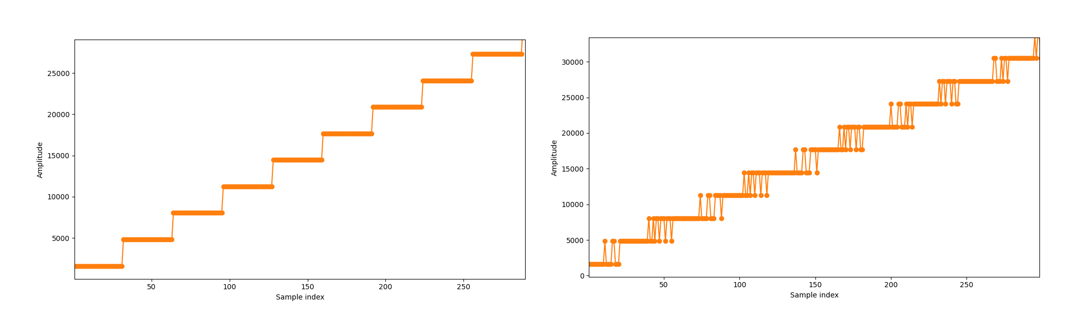
Zoom in of a low-frequency sine wave, without and with dithering.
This phase offset spreads out the spectrum distortion caused by phase truncation when reading from memory. The result is a lower peak distortion, i.e. a higher SFDR. This comes, of course, at the cost of an increased overall level of noise, i.e. a lower SNDR. Whether this tradeoff is worth it depends on the use case, and the choice is left to the user.
See Fractional phase with dithering for a system-level perspective and some performance graphs.
Pseudo-random algorithm
Dithering is implemented using a maximum-length linear feedback shift register (LFSR) from the Module lfsr. This gives a sequence of repeating state outputs that is not correlated with the phase and appears pseudo-random.
The LFSR length is at least equal to the fractional width of the phase increment.
Resource utilization
This entity has netlist builds set up with automatic size checkers in module_sine_generator.py. The following table lists the resource utilization for the entity, depending on generic configuration.
Generics |
Total LUTs |
FFs |
RAMB36 |
RAMB18 |
DSP Blocks |
Maximum logic level |
|---|---|---|---|---|---|---|
memory_data_width = 14 memory_address_width = 8 |
39 |
28 |
0 |
1 |
0 |
7 |
memory_data_width = 18 memory_address_width = 8 |
45 |
32 |
0 |
1 |
0 |
8 |
memory_data_width = 14 memory_address_width = 12 |
47 |
32 |
2 |
0 |
0 |
7 |
memory_data_width = 14 memory_address_width = 8 phase_fractional_width = 5 enable_phase_dithering = True |
54 |
51 |
0 |
1 |
0 |
7 |
memory_data_width = 18 memory_address_width = 12 phase_fractional_width = 24 enable_phase_dithering = True |
114 |
101 |
2 |
0 |
0 |
12 |
memory_data_width = 17 memory_address_width = 8 phase_fractional_width = 5 enable_first_order_taylor = True |
100 |
38 |
0 |
1 |
2 |
8 |
memory_data_width = 25 memory_address_width = 12 phase_fractional_width = 24 enable_first_order_taylor = True |
156 |
69 |
3 |
0 |
3 |
12 |
memory_data_width = 23 memory_address_width = 11 phase_fractional_width = 28 enable_first_order_taylor = True |
151 |
70 |
1 |
1 |
3 |
13 |
memory_data_width = 23 memory_address_width = 11 phase_fractional_width = 28 enable_sine = False enable_cosine = True enable_first_order_taylor = True |
161 |
70 |
1 |
1 |
3 |
13 |
memory_data_width = 23 memory_address_width = 11 phase_fractional_width = 28 enable_sine = True enable_cosine = True enable_first_order_taylor = True |
177 |
94 |
1 |
1 |
5 |
13 |
sine_generator_pkg.vhd
Package with constants/types/functions for the sine generator ecosystem.
sine_lookup.vhd
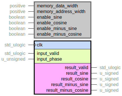
A lookup table for fixed-point sine and cosine values.
The input_phase is in range \([0, 2 \pi[\), but the memory in this entity stores only
samples for \([0, \pi / 2[\).
The phase is furthermore offset by plus half an LSB (see Quadrant handling below).
Each sample value in memory is memory_data_width bits wide.
Use the enable_* generics to specify which signals to calculate.
Enabling many is convenient when you want sinusoids that are perfectly \(\pi / 2\)-offset
from each other.
Enabling further signals will not require any extra memory, but it will add logic.
Also, sine calculation (positive or negative) requires one memory read port, while cosine
calculation (positive or negative) requires another.
So enabling any sine along with any cosine will require two memory read ports.
Quadrant handling
Consider the unit circle, and the sine and cosine plots in the picture below.
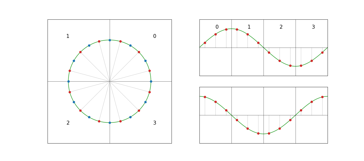
Overview of the four quadrants.
When implementing an angle-discrete sine lookup table, the first approach might be to use the blue points in the plot above, starting at phase zero. However, for the implementation to be efficient, we want to be able to calculate e.g. sine in quadrant one as the sine in quadrant zero, but read out in reverse order. This is desirable since “reverse order” when working with fixed-point numbers simply means a bit-wise inverse of a “normal order” counter.
With this goal of efficient implementation in mind, we offset the phase so that the points are mirrored around \(0\), \(\pi/2\), \(\pi\) and \(3 \pi/2\). The resulting symmetry can be clearly seen in the sine and cosine plots above. For example, the sine points in quadrant one are clearly the same points as in quadrant zero, but in reverse order. Apart from this ocular hint, we can also show it using basic trigonometric identities:
This shows how both sine and cosine for all four quadrant can be calculated using only sine values from the first quadrant (\([0, \pi/2]\)). In the calculations above we have utilized the fact that a phase of \(\pi/2 - \theta\), meaning phase in reverse order, is the same as bit-inversion of the phase.
Fixed-point representation
When we want to distribute \(2^\text{memory_address_width}\) number of points over the phase range \([0, \pi / 2[\), we use
To achieve the symmetry we aim for in the discussion above, we offset the phase by half an LSB:
This gives a total phase of
We also have an amplitude-quantization given by the memory_data_width generic.
This gives a maximum amplitude of
With this established, we can calculate the memory values as
As can be seen in the trigonometric identities above, the resulting output sine value from this entity is negated in some some quadrants. This gives an output range of \([-A, A]\). Where fixed-point \(A\) is equivalent to floating-point \(1.0\).
Performance
Samples in memory are stored with memory_data_width bits, and the quadrant handling discussed
above adds one more sign bit.
The only source of noise and distortion is the digital quantization noise when storing sine
values with a fixed-point representation in memory.
Hence the result from this entity has SNDR and SFDR equal to memory_data_width + 1 ENOB.
taylor_expansion_core.vhd
Core that calculates the first-order Taylor expansion of sinusoid function
with fixed-point numbers that fit in a DSP48. This core is to be used in sine_calculator.vhd, and is not really suitable for other purposes.
Warning
This is an internal core. The interface might change without notice.